The diagram above illustrates the energy flow logic during AC charging, divided into two parts: "charger side" and "vehicle side". The core function of the OBC is to convert alternating current (AC) into high-voltage direct current (HVDC) for charging the battery.
To facilitate understanding of the OBC's connection in the vehicle system, the following vehicle system block diagram presents the relationship network of the OBC in the entire vehicle.
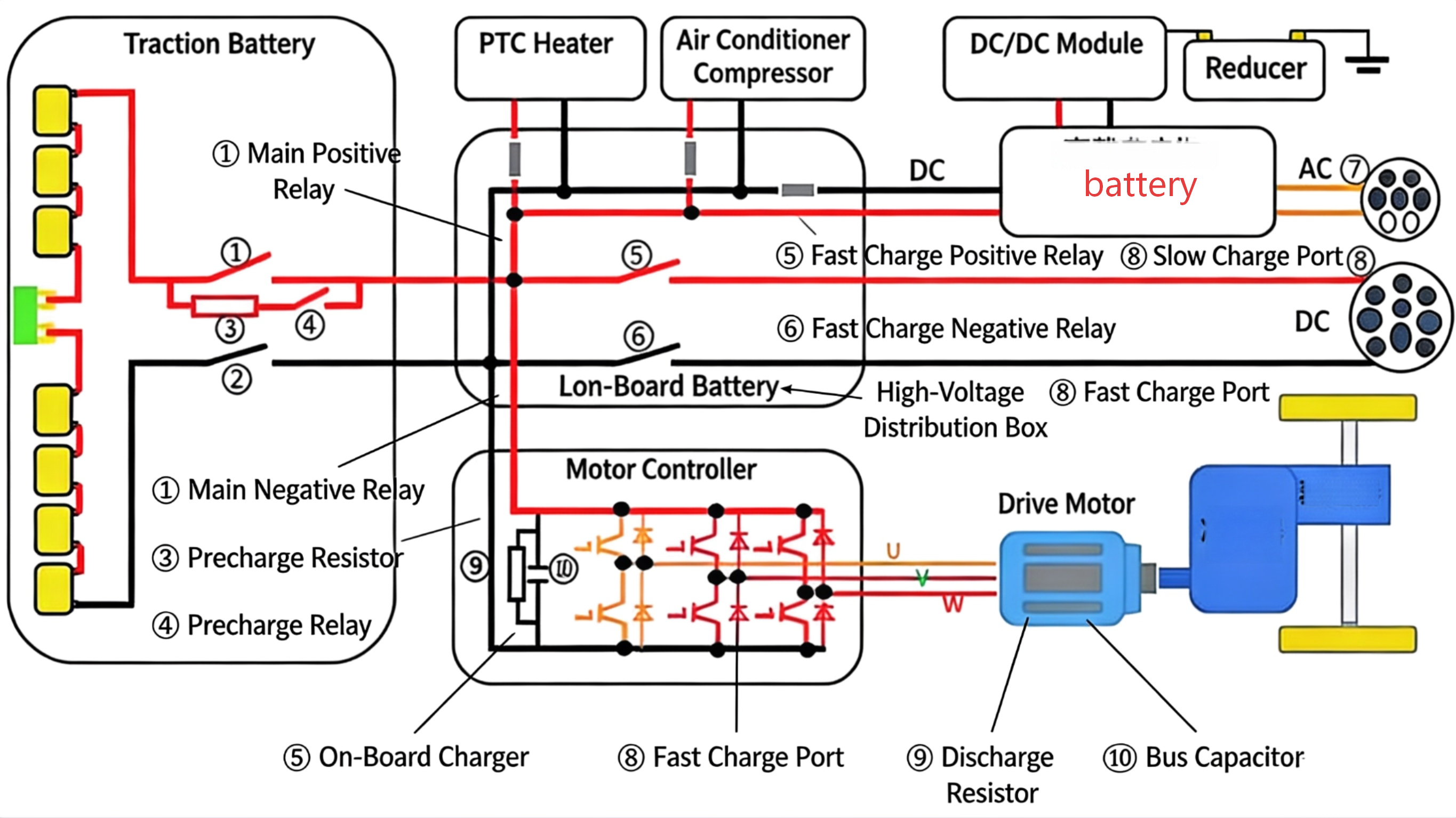
The AC charging port serves as the interface between the OBC and external AC charging equipment.
- Phase line (L) and neutral line (N) introduce AC power.
- Protective earth (PE) ensures electrical safety.
- Connection Confirmation (CC) and Control Pilot (CP) realize connection status detection and charging control signal interaction.
- The 12V auxiliary power supply powers the internal circuits of the OBC.
- High-Voltage Interlock (HVIL) input/output is used for abnormal detection and protection of the high-voltage system.
- The charging request signal is sent by the relevant control unit to put the OBC into charging state.

Note: The recipient of CC and CP signal input for detection is determined by the system. Different vehicles have different designs, subject to the specific vehicle wiring.
The converted DC power is transmitted to the battery pack through the power distribution box. The Battery Management System (BMS) real-time monitors the battery status (voltage, current, temperature, State of Charge (SOC), etc.) and transmits it to the OBC, Vehicle Control Unit (VCU) and instrument panel via the CAN bus. The OBC adjusts charging parameters according to the BMS feedback to achieve intelligent charging management.
The AC charging system mainly consists of AC charging equipment, high-voltage wiring harnesses, AC charging ports, on-board chargers, high-voltage distribution boxes, traction battery packs, battery management systems and other components.
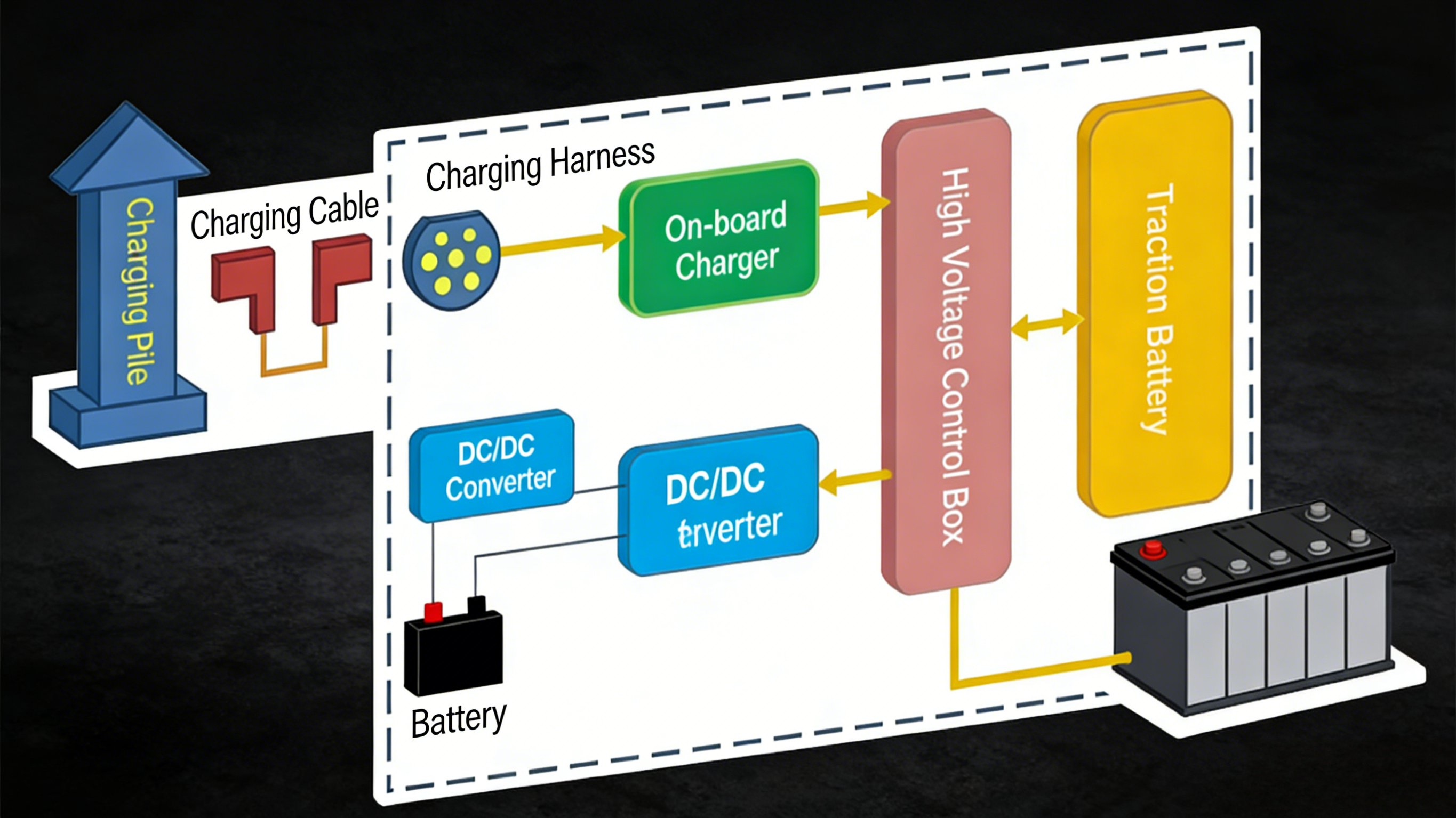
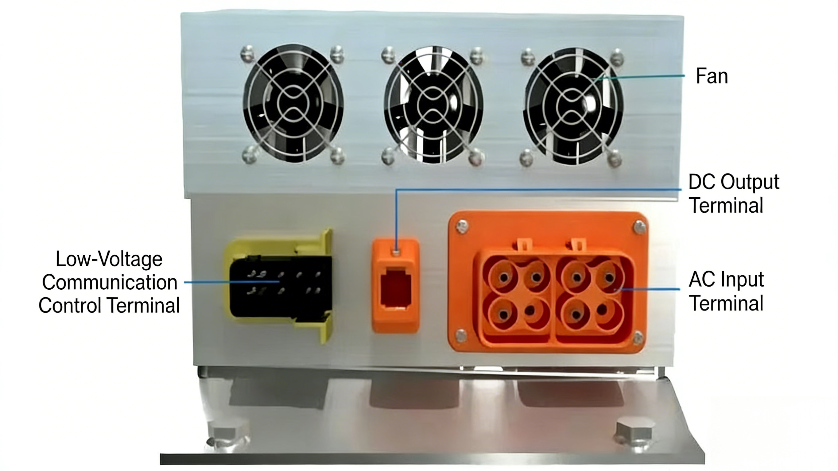
The on-board charger is connected to the AC charging port upstream and the high-voltage control box downstream. It also communicates with the Vehicle Control Unit (VCU), Battery Management System (BMS) and other systems. Externally, it is equipped with DC output terminals, AC input terminals, low-voltage communication terminals, heat sinks and cooling fans.
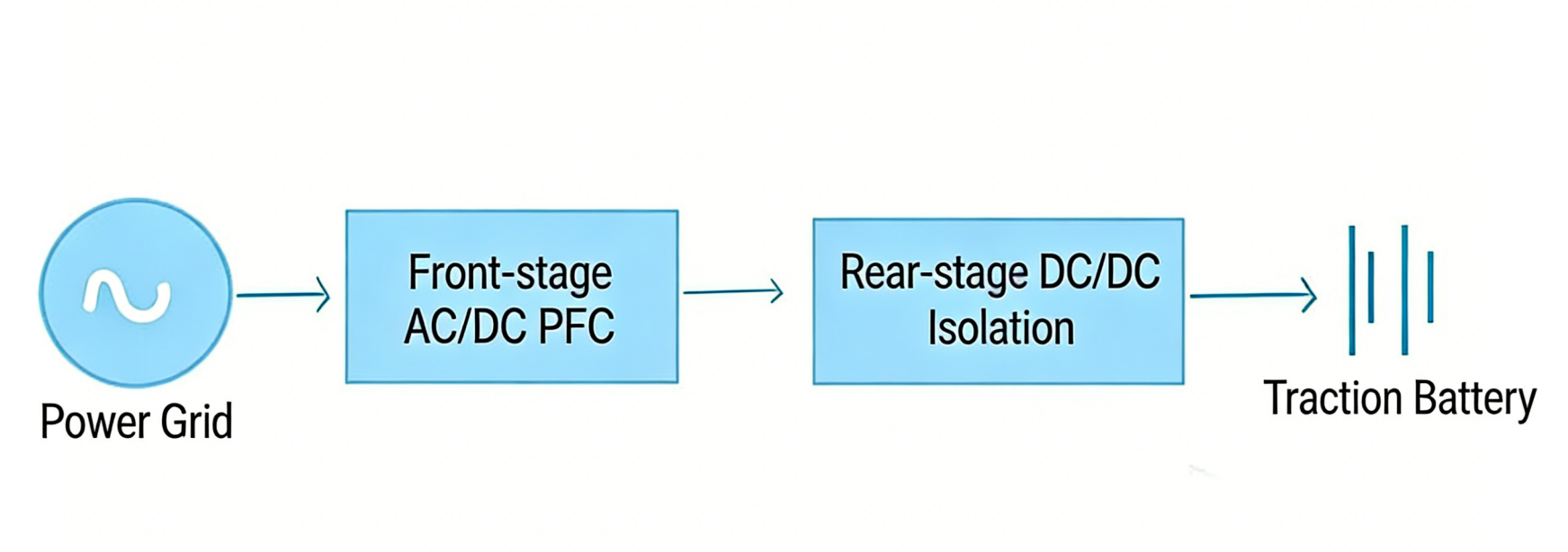
How does the charger convert 220V AC into high-voltage DC? It generally adopts a two-stage structure:
- PFC circuit: Used for power factor correction. High-power electrical appliances without PFC will affect the power grid.
The conversion circuit block diagram is as follows (PFC + LLC):
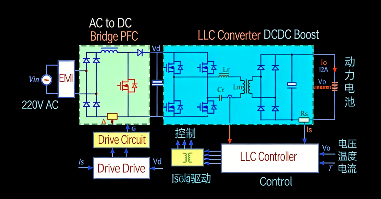
- Front-stage PFC: Converts AC to DC.
- Rear-stage LLC (isolated DC-DC converter): Converts DC to the required DC.
Note: The function of the DC-DC converter here is to adjust the DC voltage output by the PFC to match the charging voltage of the power battery (such as 400V/800V). This DC-DC converter is different from the one that converts high voltage to 14V low voltage.
Both the front-stage bridgeless PFC circuit and the rear-stage LLC circuit require a controller for control. Isolated driving controls the switching of the four switching tubes.
The on-board charger first processes the 220V AC through the input protection circuit, including eliminating differential mode and common mode interference, overvoltage protection, and controlling the discharge speed of the capacitor. This protects the circuit and prevents voltage mutations.
Subsequently, the AC is converted to DC through the rectifier circuit, outputting 310V DC. Then, the PFC boost circuit uses power factor correction technology to improve power efficiency and reduce energy waste, boosting the 310V DC to approximately 400V DC.
Finally, the DC-DC conversion circuit converts the DC power into the DC power required by the power battery. After passing through the output EMI and protection circuit, it provides stable and safe DC power supply for the power battery.


