What happens when you place a mobile phone near a speaker that's playing music? The speaker emits a hissing noise.
This is because mobile phones transmit and receive radio waves when in operation, and the internal circuits of the speaker are prone to such Electromagnetic Interference (EMI). The interfering signals are picked up and amplified by the speaker's circuits, and finally converted into audible noise through the loudspeaker, which affects the sound quality.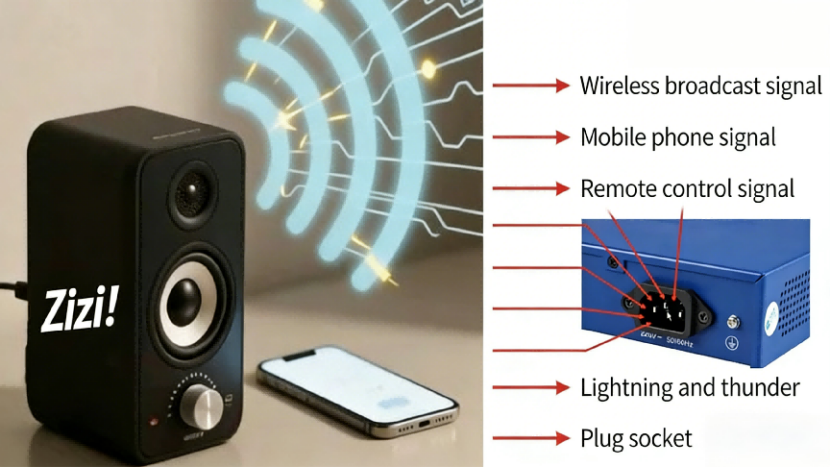
Facing the prevalent electromagnetic interference (EMI) issue, how to build a defensive barrier to "purify" the power supply and ensure stable equipment operation is precisely the core significance of EMI rectifier filter circuit design.二The figure below shows a typical rectifier filter circuit. Its main function is to perform preprocessing such as filtering and rectification on the input 220V alternating current (AC), providing a 311V direct current (DC) voltage for the subsequent stage circuit.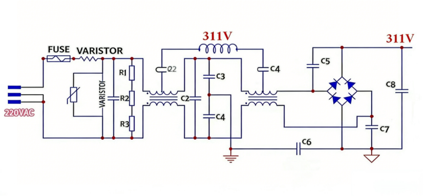
Functions of each circuit component:
① Fuse: Overcurrent protection. It fuses when the circuit is short-circuited or overloaded, cutting off the loop to protect subsequent components.
② NTC (Negative Temperature Coefficient) Thermistor: Suppresses inrush current during startup. It has a high resistance at room temperature, limiting the large current for capacitor charging at the moment of power-on. After the circuit operates normally, its resistance decreases due to self-heating, reducing power consumption. (Application Limitation: If there is an instantaneous power outage followed by rapid re-power-on, the NTC’s temperature does not drop sufficiently and its resistance fails to recover to the high room-temperature value, leading to a significant reduction in inrush current suppression effect. It usually needs to be paired with relays, PTCs, or other components for redundant design.) At the moment of power-on, capacitor C8 is approximately short-circuited, which will cause a large inrush current that may damage circuit components such as the fuse and rectifier bridge.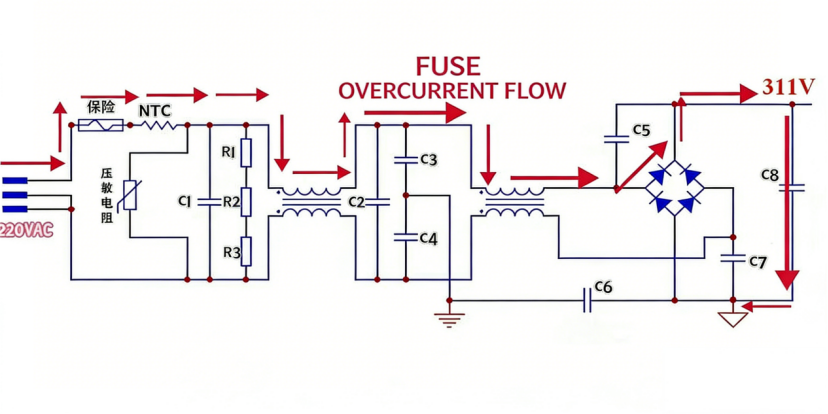
In the above circuit, a negative temperature coefficient thermistor (NTC, typically 5-20Ω) acts as a current-limiting resistor, thus restricting the inrush current in the circuit.
③ Varistor: Overvoltage protection. When the power grid voltage rises abnormally (e.g., lightning strikes, surges), its resistance decreases sharply to discharge overvoltage energy, protecting the subsequent circuit from overvoltage damage.
④ Capacitor C1 forms a "π-type" filter with Transformer 1 (common-mode inductor) and C2. Capacitors C2, C3 form an "LC" filter with Transformer 2. Their main function is to filter out high-frequency harmonics in the alternating current.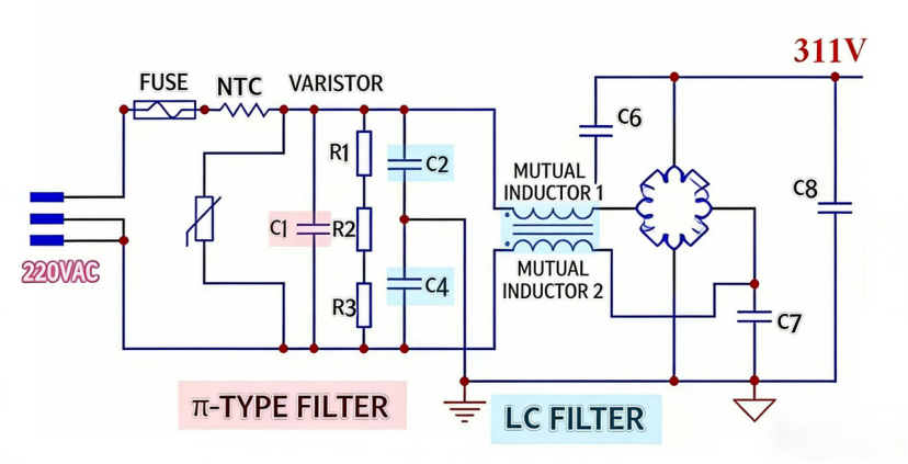
Question: Why is EMI filtering necessary?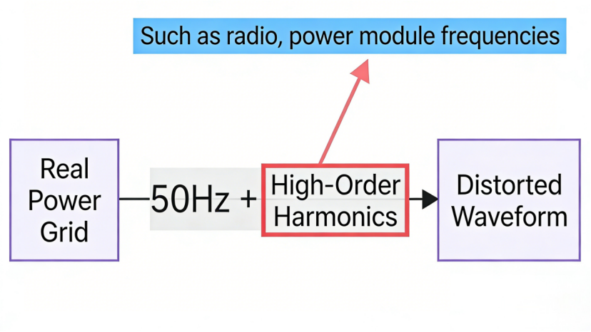
The actual power grid output contains a 50Hz fundamental wave and high-order harmonics (e.g., harmonics of frequencies from radio, power modules, etc.), forming a distorted waveform together. These high-order harmonics will interfere with the normal operation of subsequent loads and affect the power quality of the power grid. EMI filter circuits and other circuits are required to filter out high-frequency harmonics using the frequency characteristics of capacitors and inductors, providing nearly pure 50Hz fundamental wave power for the subsequent circuit and ensuring stable equipment operation.
⑤ R1, R2, R3 Bleeder Resistors: When the power is cut off, they discharge the charge stored in the capacitors, avoiding electric shock risks caused by residual high voltage in the capacitors or inrush current during the next power-on.
Question: Why are there 3 resistors here?
Due to the insufficient power and voltage resistance of a single resistor, three resistors in series can divide the voltage, keeping the voltage and power borne by each resistor within the rated range to avoid damage. At the same time, series connection improves the overall voltage resistance and power-carrying capacity to meet the circuit requirements.
⑥ X-Capacitors (C1, C2): Connected between the live wire and neutral wire, they are specially designed to filter out differential-mode interference (interference signals between the live wire and neutral wire) and suppress differential-mode noise generated by load changes on the power line. They generally have a large capacity.
⑦ Y-Capacitors (C3, C4): Connected between the live wire/neutral wire and the ground wire, they target common-mode interference (interference of the live wire and neutral wire relative to the ground wire), can weaken common-mode noise introduced by electromagnetic induction, and have high safety requirements, needing to meet safety standards such as voltage resistance and leakage current. The combination of the two can improve the electromagnetic compatibility of the power input, make the equipment more stable, and comply with relevant electromagnetic radiation regulations.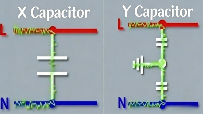
X-capacitors and Y-capacitors are collectively referred to as safety capacitors (with small leakage current). X-capacitors are generally film capacitors, and Y-capacitors are generally blue high-voltage ceramic capacitors.
⑧ Capacitors C5, C7: C5 absorbs surge voltage, and C7 smooths the voltage and reduces current mutations, both indirectly protecting the diodes.
EMI Rectifier Circuit
A rectifier bridge is an electronic circuit component used to convert alternating current (AC) to direct current (DC). The 220V alternating current passes through the rectifier bridge. Utilizing the one-way conductivity of the four diodes, different diodes conduct during the positive and negative half-cycles of the alternating current, making the current flow through the load in the same direction at all times and converting the alternating current into pulsating direct current. The voltage waveform is then smoothed by the filter capacitor.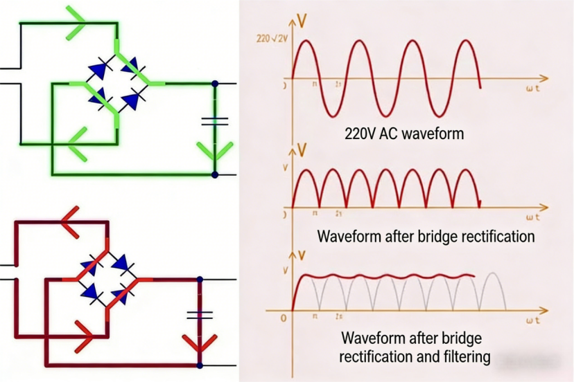
1.Uo (311V) = Ui (220V) * 1.414 (square root of 2)
2.The maximum voltage that a single diode can withstand should be greater than twice the output voltage (2.8 times the effective value of the input voltage). The maximum current that a single diode can withstand should be greater than half of the output current. Because in each cycle, only two diodes work, that is, each diode only works for half a cycle, so the current passing through it is only half. As for the voltage, when the diode is reverse-biased, it needs to withstand the sum of the voltage of the subsequent filter capacitor and the input terminal, which is twice the output voltage. These parameters need to be considered when selecting a rectifier bridge.


