To better understand the automotive DC-DC converter, it is necessary to learn some relevant basic knowledge.
A DC-DC Converter refers to a device that can convert one level of DC input voltage (or current) into another level of DC output voltage (or current).
There are two types of conversion technologies applied in DC/DC module conversion: one is the linear regulation mode (LDO); the other is the switching regulation mode (DC-DC). At present, the switching regulation mode is most commonly used in electric vehicles.

Below is a brief illustration taking BUC as an example, so as to gain a better understanding of the basic structure of DC-DC converters. Introduction to other types of DC-DC converters will be provided subsequently.
Question: How to adjust the output voltage to further dim the light bulb?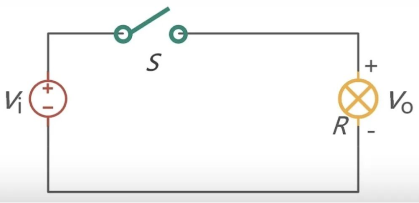
Answer: Dimming can be achieved by means of chopping, which involves periodically turning the switch on and off. The bulb lights up when the switch is on and turns off when the switch is off. If the switch is adjusted fast enough—so fast that the human eye cannot perceive the changes—dimming can be realized.
When the on-time within a cycle is longer, the bulb will be brighter; conversely, when the off-time within a cycle is longer, the bulb will be dimmer.
The frequency range of sound audible to the human ear is 20–20000 Hz. Therefore, the switching frequency is generally designed to avoid this frequency range in order to reduce noise.
What is chopping?
For a chopper circuit with a given input voltage, as shown in the figure.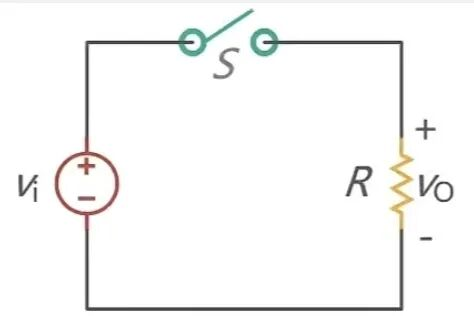
The average value of its output voltage is achieved by periodically opening and closing the switch in the circuit.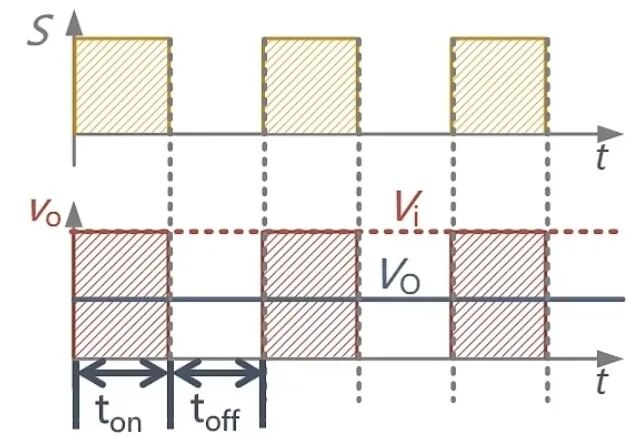
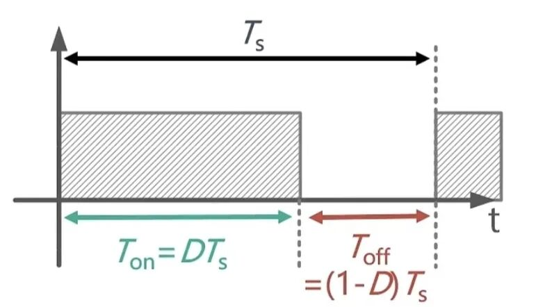
The periodicity involves the concept of duty cycle, that is, for each switching cycle Ts, the on-time is Ton, the off-time is Toff, and the duty cycle is denoted as D, then: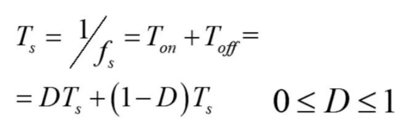
It consists only of a DC voltage source, a switch S and a load R. The DC voltage source is used as the input with a voltage of V, while the voltage Vo across the load R is taken as the output voltage. The switch S is operated at a certain frequency.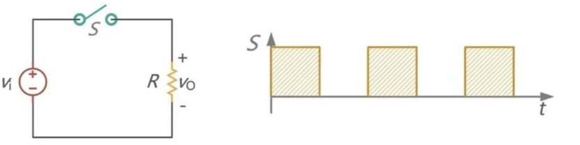
If the switch is subjected to periodic control, the output voltage will be equal to Vi when the switch is turned on, and equal to 0 when the switch is turned off. The average value of the output voltage calculated over one cycle is: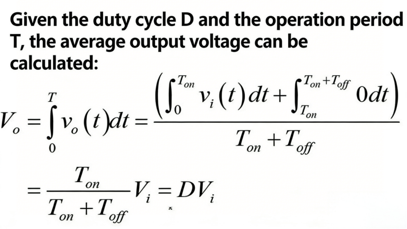
In the circuit described above, voltage regulation is realized by turning the switch on and off, which leads to large fluctuations in the output voltage. How can we smooth the output voltage?
This goal can be achieved by connecting a capacitor in parallel, which is intended to modify the output and make it much smoother.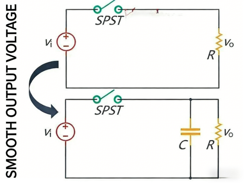
Then comes the question: From the perspective of capacitor characteristics, the voltage across a capacitor cannot change abruptly, as described by the formula i=C.dtdU. If the voltage changes abruptly, an extremely large current will be generated. Therefore, under normal circumstances, a voltage source cannot be directly connected to a capacitor, nor can a current source be directly connected in series with an inductor.
So, what methods can be used to suppress the current surge?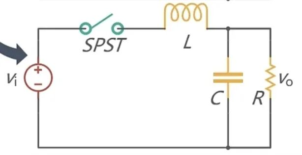
Connect an inductor in series to suppress current surges, because the current through an inductor cannot change abruptly. When the switch is turned on, the presence of the inductor prevents the current from changing abruptly. When the switch is turned off, an inductor cannot allow its current to be interrupted, so it is necessary to provide a freewheeling circuit for the inductor.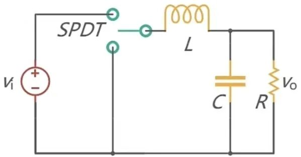
Replace the single-pole single-throw (SPST) switch with a single-pole double-throw (SPDT) switch, and the freewheeling circuit can be realized through switch commutation. However, it is impossible to switch the switch manually all the time, and the introduction of power devices can easily solve this problem.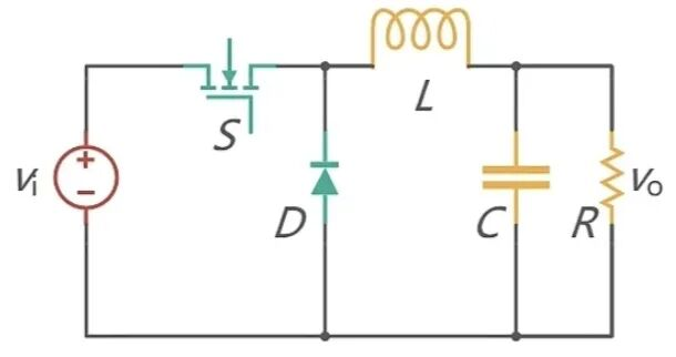
Now let’s look at the DC-DC converter in EVs, and we will gain a clearer understanding of the filter circuit.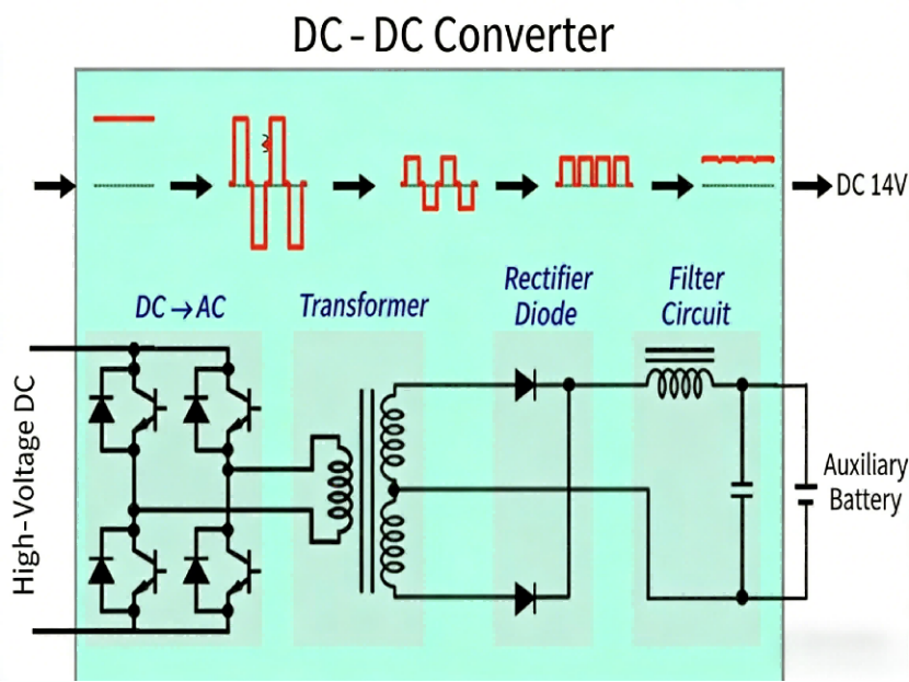
The high-voltage direct current from the traction battery passes through the high-voltage distribution box and enters the transformer of the DC/DC conversion module. The internal gate drive switch circuit chops the high-voltage direct current into square waves (pulse waves). The duty cycle of the square waves is adjusted by the PWM controller to regulate the output power of the transformer, which then goes through the filter and rectifier circuit to output low-voltage direct current for supplying power to the low-voltage storage battery and low-voltage electrical equipment.
The output voltage is compared with the reference voltage. If the deviation between the actual output voltage and the reference voltage is significant, the DC/DC controller will drive the gate switch to adjust the duty cycle, thereby regulating the output voltage.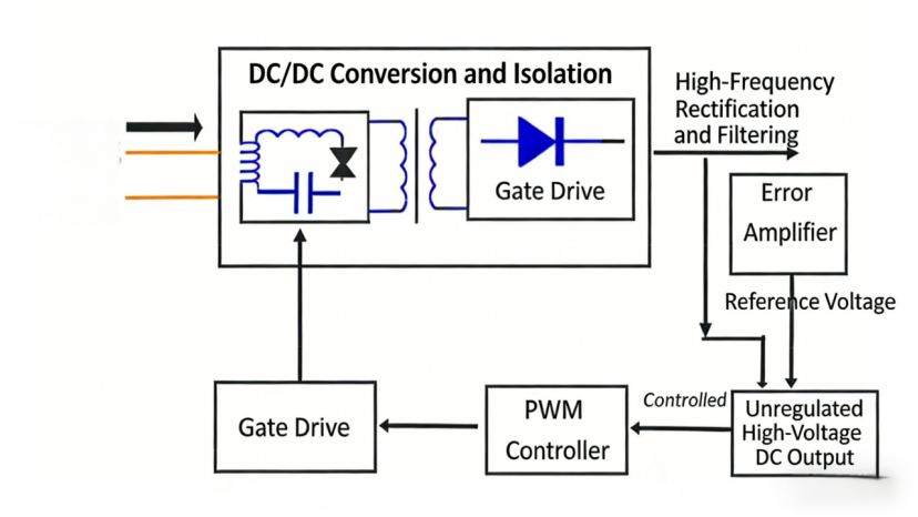
The working principle diagram is shown below, where RL represents the load, Cf the filter capacitor, and Lf the filter inductor. The dashed-line part is the sampling circuit.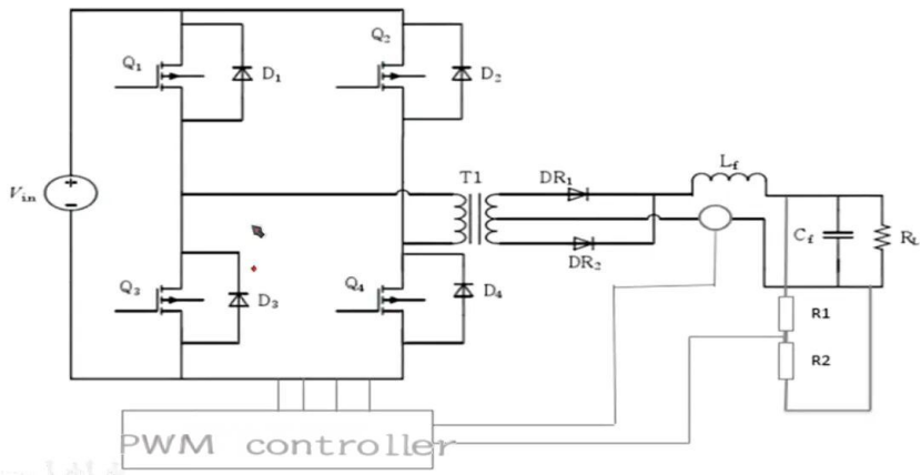
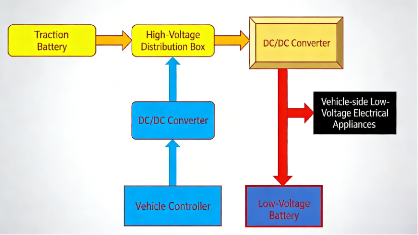
The electrical energy from the traction battery pack of the electric vehicle passes through a high-voltage distribution box, and then the DC-DC converter converts the high-voltage direct current into low-voltage direct current, which is supplied to the low-voltage electrical appliances and the low-voltage storage battery on the vehicle.
The DC-DC converter requires an enable signal (which permits operation and is typically a 12V high level). When the vehicle is powered on successfully, the vehicle control unit (VCU) starts to output a 12V enable signal to allow the DC-DC converter to operate.
EV200 Control Schematic Diagram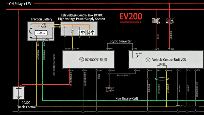
Operating Procedure of the EV200 DC/DC Converter
Method for Judging Whether the DC/DC Converter Is Operating
Step 1: With the vehicle wiring harness properly connected, use a multimeter to measure and record the terminal voltage of the lead-acid battery before powering on the vehicle
Step 2: Power on the vehicle to the ON position, continue to read the multimeter value and observe the changes. If the value is between 13.8 V and 14 V, it can be judged that the DC/DC converter is operating.


