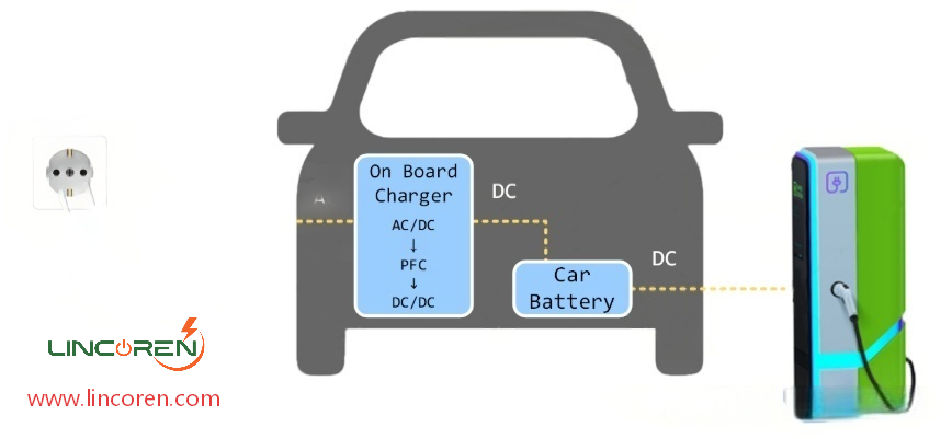
800V on-board chargers (OBCs) are undergoing steady development, delivering fast and ultra-fast charging capabilities for electric vehicles (EVs). However, the transition from existing 400V OBCs to 800V systems directly impacts the selection of semiconductor devices, diode bridges, microcontroller units (MCUs), and transformers within the OBC.
This article explores these four key components, providing insights for engineers transitioning to 800V OBCs in electric vehicles.
400V EV OBCs can employ mature silicon-based MOSFETs, which typically feature a standard rated voltage of 650V. In contrast, 800V EV OBCs require MOSFETs with an elevated voltage rating, as they need to achieve a blocking voltage capability of 1200V.
Wide-bandgap (WBG) devices, such as silicon carbide (SiC)-based MOSFETs, have emerged as viable alternatives thanks to their 1200V rated voltage. SiC MOSFETs offer several advantages over silicon MOSFETs, including higher breakdown voltage, lower on-resistance, improved heat dissipation, and higher switching frequency.
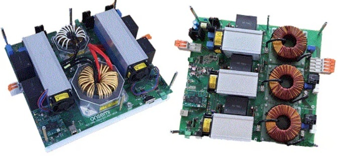
Nevertheless, gallium nitride (GaN) is rapidly competing with SiC technology, driven by its superior switching frequency. A notable example is the 11 kW/800V OBC utilizing GaN transistors announced by Infineon Technologies at APEC 2023. The company claims that this OBC outperforms its SiC counterparts, boasting a 36% higher power density.
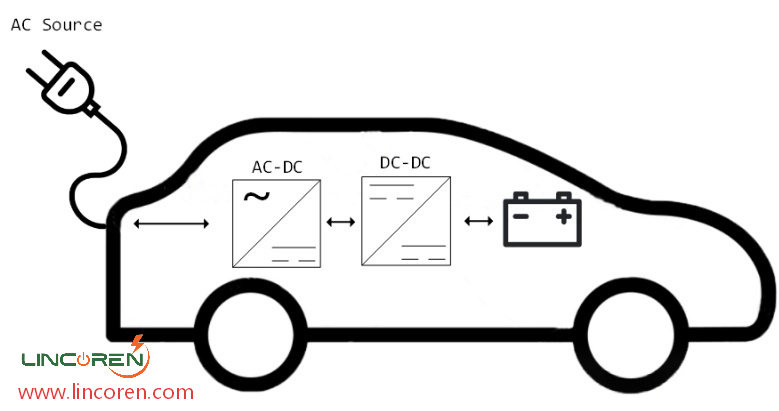
When an 800V OBC is connected to a 120V or 240V grid, the diode bridge in the AC/DC converter stage must be rated to handle the increased voltage. The required rated voltage of the diode bridge doubles compared to that of 400V OBCs. However, the elevated desired rated voltage of the diode bridge does not necessarily translate to higher power losses.
In 800V OBCs, the transformer turns ratio is typically doubled to compensate for the higher battery voltage. This adjustment halves the current in the transformer’s secondary winding, cutting the overall copper loss of the transformer by half. The reduced current flowing through the secondary winding also lowers the power loss in the diode bridge.
Diode bridges suitable for 800V OBCs can have lower internal resistance than those used in 400V OBCs, thereby reducing conduction losses. A comparative example is provided by STMicroelectronics’ STPSC2006CW (600 V) and STPSC15H12 (1200 V) SiC diodes: the latter has an internal resistance of 66 mΩ, while the former has a rated resistance of 84 mΩ.
When opting for a higher-voltage EV powertrain, the MCU is a component often overlooked in OBC design. While MCUs used in 400V OBC EV powertrains may seem applicable to 800V systems, MCUs with higher-resolution analog-to-digital converters (ADCs) are essential.
Even before delving into EV-specific MCUs, it is clear that conventional MCUs used in internal combustion engine (ICE) vehicles are not suitable for EVs, as illustrated in Figure 4. The advent of WBG devices, which demand higher switching frequencies, has created a definitive need for sophisticated MCUs in electric vehicles.
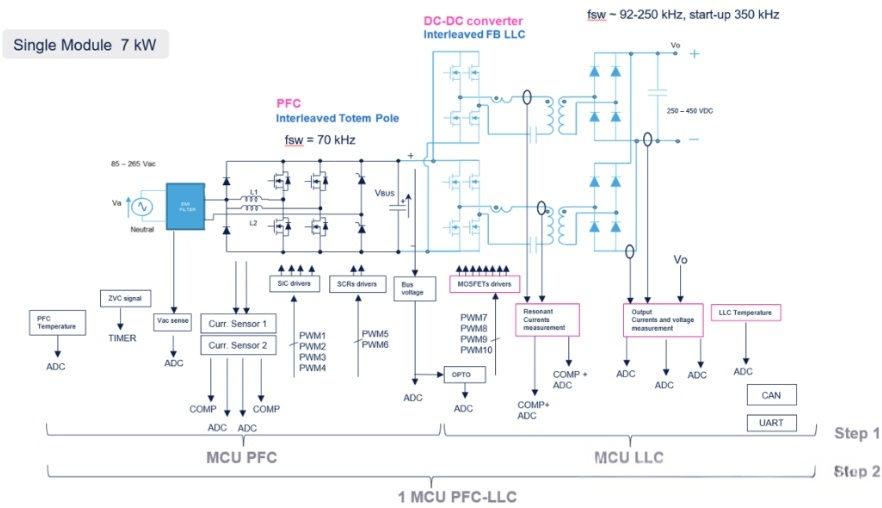
As shown in the figure, the MCU plays a prominent role in controlling the power factor correction (PFC) and LLC resonant converter stages of the OBC. In both stages, the 800V voltage must be handled at either the input or output of the converter. Therefore, when transitioning from 400V to 800V, the ADC must have higher resolution to effectively regulate the pulse-width modulation (PWM) signals fed to the semiconductor switches. In addition, MCUs equipped with higher-resolution ADCs—such as the 12-bit resolution of the Stellar E1—enable efficient voltage and current sensing.
In 800V OBCs, the transformer turns ratio (n = N2/N1) is generally twice that of 400V OBCs. This adjustment is necessary to compensate for the higher battery voltage while maintaining similar voltage and current waveforms on the primary side.
The halved amplitude of the secondary current allows the use of thinner secondary windings. The reduction in cross-sectional area facilitates fitting the windings into the core window and lowers conduction losses. However, according to one study, the transformer’s iron loss is not significantly affected since the magnetic flux density remains unchanged.
The demand for fast and ultra-fast charging in electric vehicles is driving manufacturers to develop OBCs with higher power ratings. While research continues to enhance the power density of existing 400V OBCs, 800V OBCs open up new opportunities to support faster EV charging.
Nevertheless, attention must be paid to the ratings of WBG semiconductor switches, diodes, and transformers. MCUs must be equipped with ADCs of higher resolution to accommodate the wide voltage swing in 800V OBCs.
 Diode Bridges
 Microcontroller Units (MCUs)

 800V on-board chargers (OBCs) are undergoing steady development, delivering fast and ultra-fast charging capabilities for electric vehicles (EVs). However, the transition from existing 400V OBCs to 800V systems directly impacts the selection of semiconductor devices, diode bridges, microcontroller units (MCUs), and transformers within the OBC.
 Nevertheless, gallium nitride (GaN) is rapidly competing with SiC technology, driven by its superior switching frequency. A notable example is the 11 kW/800V OBC utilizing GaN transistors announced by Infineon Technologies at APEC 2023. The company claims that this OBC outperforms its SiC counterparts, boasting a 36% higher power density.
 As shown in the figure, the MCU plays a prominent role in controlling the power factor correction (PFC) and LLC resonant converter stages of the OBC. In both stages, the 800V voltage must be handled at either the input or output of the converter. Therefore, when transitioning from 400V to 800V, the ADC must have higher resolution to effectively regulate the pulse-width modulation (PWM) signals fed to the semiconductor switches. In addition, MCUs equipped with higher-resolution ADCs—such as the 12-bit resolution of the Stellar E1—enable efficient voltage and current sensing.


